My first JDM build complete was based on the “$135 NAS Killer”.
Then, lurking around on “The Discord”, as we all know there is one true Discord channel, I got the build itch, so built a rig based on the “Entry Level Rackmount” build. I meant to write a build complete article in the /JDM sub-Reddit but never got around to it.
The Supermicro X8DT6-F motherboard has been a dream. I started with dual Xeon L5640’s but wanted a boost, so landed on dual Xeon X5670’s. And with 48 GB of DDR3 ECC RAM, this server does everything I need and then some. All of this, wrapped up in a Rosewill L4500 rack mounted chassis and installed in a StarTech 25U server rack, makes the perfect setup for me.
But, as you’ve been in the JDM world for a while now, you can imagine after upgrading drive density even a 15-bay Rosewill quickly gets too small. So, I built a 20 bay L4500 Rosewill DAS, with expandability to 25 bays.
Here is the completed DAS:
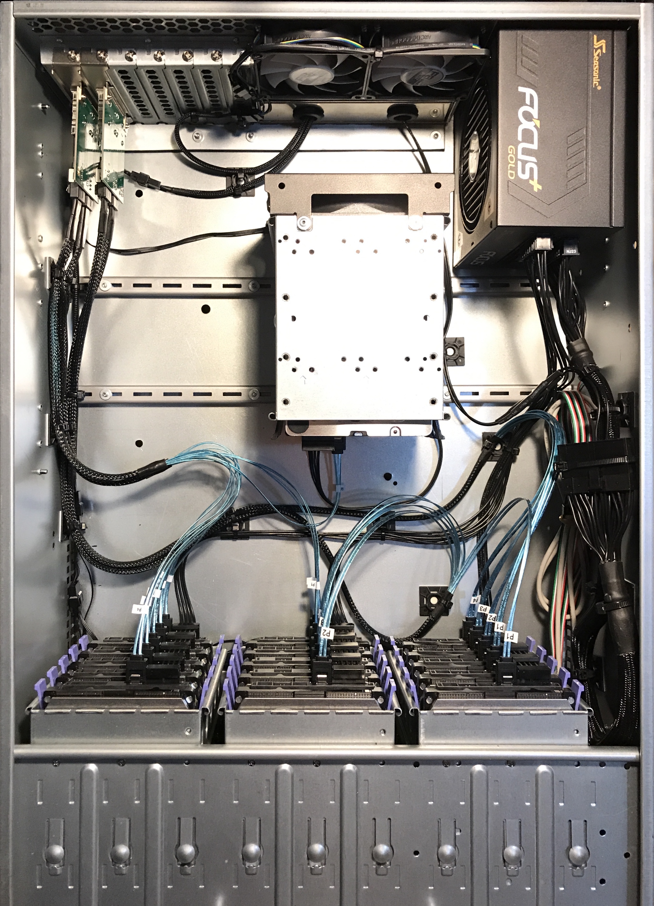
Notice the clean, easy cable management of the standard 3x5 front cage setup. Plenty of room. An additional 5 bays is achieved with the rear mounted cage ordered from eBay, providing a total of 20 bays. An additional 5-bay cage can be placed to the left of this cage bringing the total bays to 25.
My initial plan was to turn the 15-bay Rosewill into a 30-bay Rosewill. But after getting my hands in the case, moving drive cages around and playing with cable management, I believe the 20-bay or 25-bay is a nice compromise, allowing for much cleaner and easier cable management.
The fan is mounted backwards in this add-on cage to maintain front to back airflow. And there is enough room to slide drives in and out of this cage without removing the cage. I planned this so I could rivet the cage in place permanently. Though, if you’ve worked with pop rivets before, you know they can be drilled out if needed.
When initially installing the cage on the bottom of the Rosewill case, there was too much vibration and flex, so I found inexpensive steel in the form of 24" Single Slot Standards from Menards for $1.99 each. Two of them cut to around 17" made for a very rigid backbone to support two cages and 10 drives.
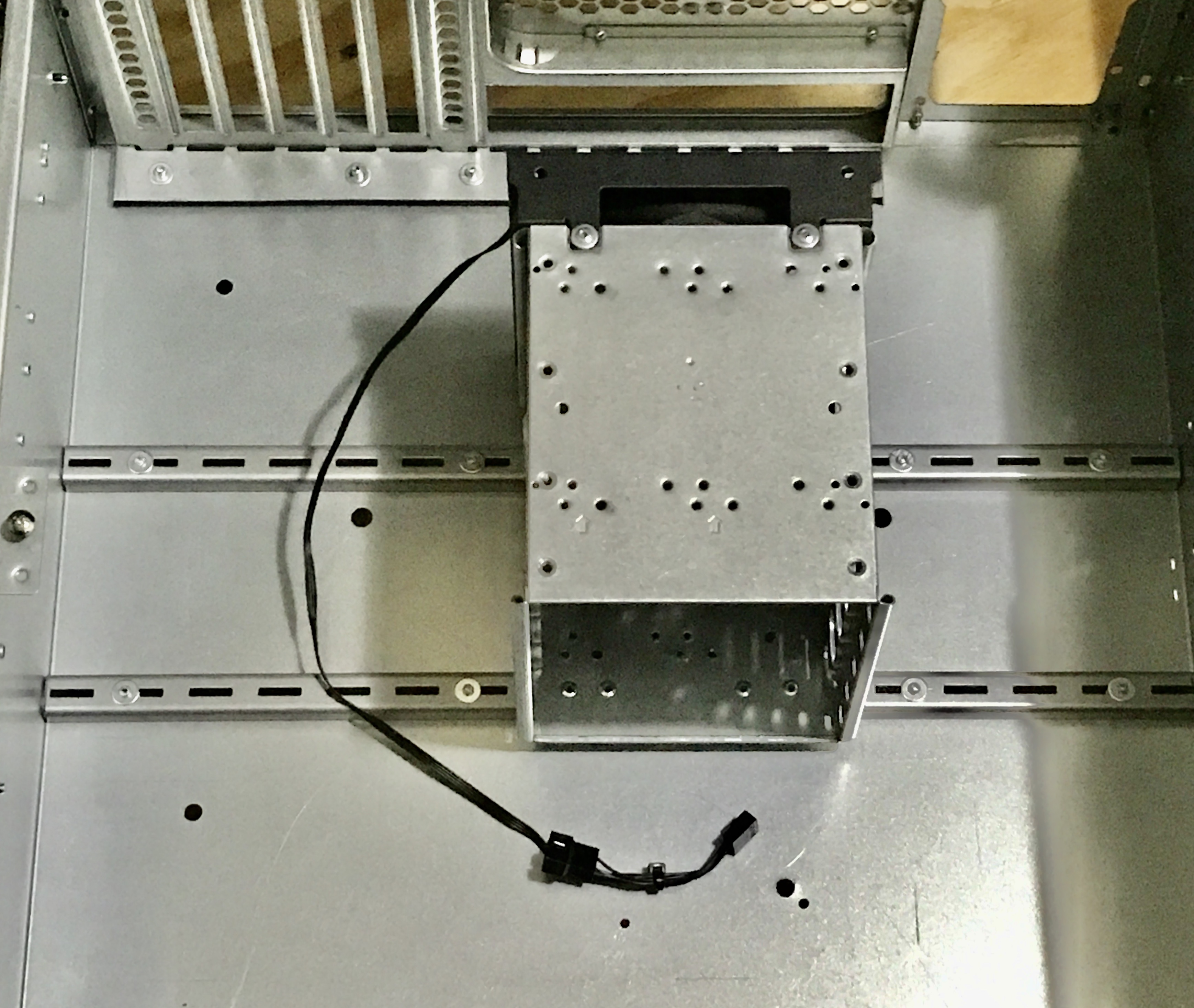
As you can see in the photo above, the steel shelf standard is riveted to the bottom of the case, and the cage is riveted to the standard.
Notice the rivet washers on the underside of the slots in the photo above. These provide a little extra hold. Also, you’ll notice the front fan shroud is riveted to the hard drive cage. I decided to do this after receiving incorrectly sized screws for the threads. The rivets provide a very tight, trouble free fitment, while the rivet washers reduce the length of rivet inside the cage, ensuring that the rivets do not touch the hard drives.
The fan screws can be accessed, when needed, by removing the hard drives. If I were to do this again, I would screw the fan to the front grill instead, thus eliminating the need for removing the hard drives, as the fan screws could be removed with a stubby screwdriver. The fan easily slides out the side of the front grill.
The motherboard tray is conspicuously absent from these photos. In order to make layout of hard drive cages freer and easier, but make use of the rear PCIe slots, I had to remove the motherboard tray, cut it and then reinstall the rear 1.5" of tray to provide a fastening for the bottom of the PCIe slots.
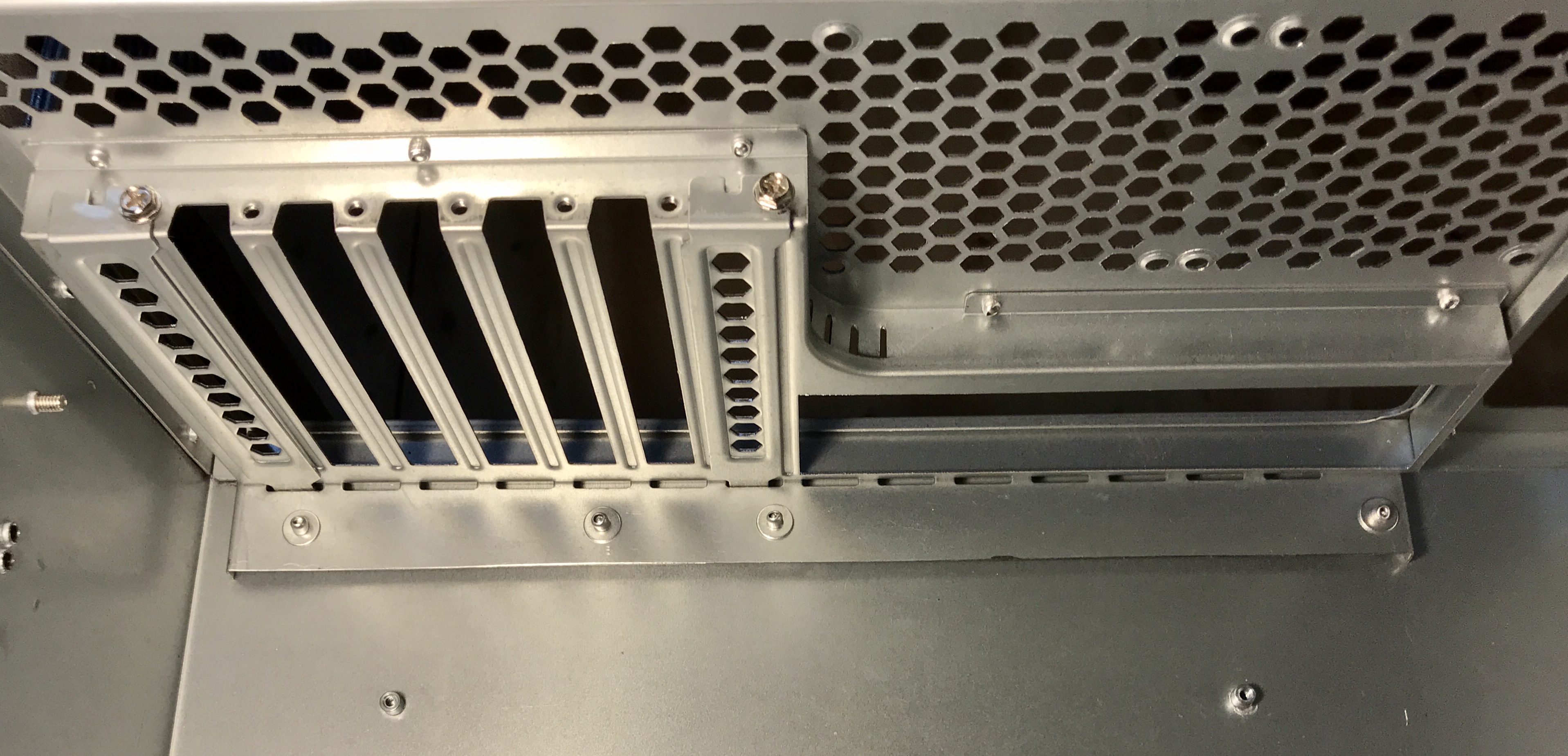
Again, I made use of rivets and rivet washers below. The threaded insert near the bottom of the photo is one of four mounting points for the motherboard tray which I eventually drilled out with a 1/4" twist bit to provide a smooth surface for layout and mounting the new cage.
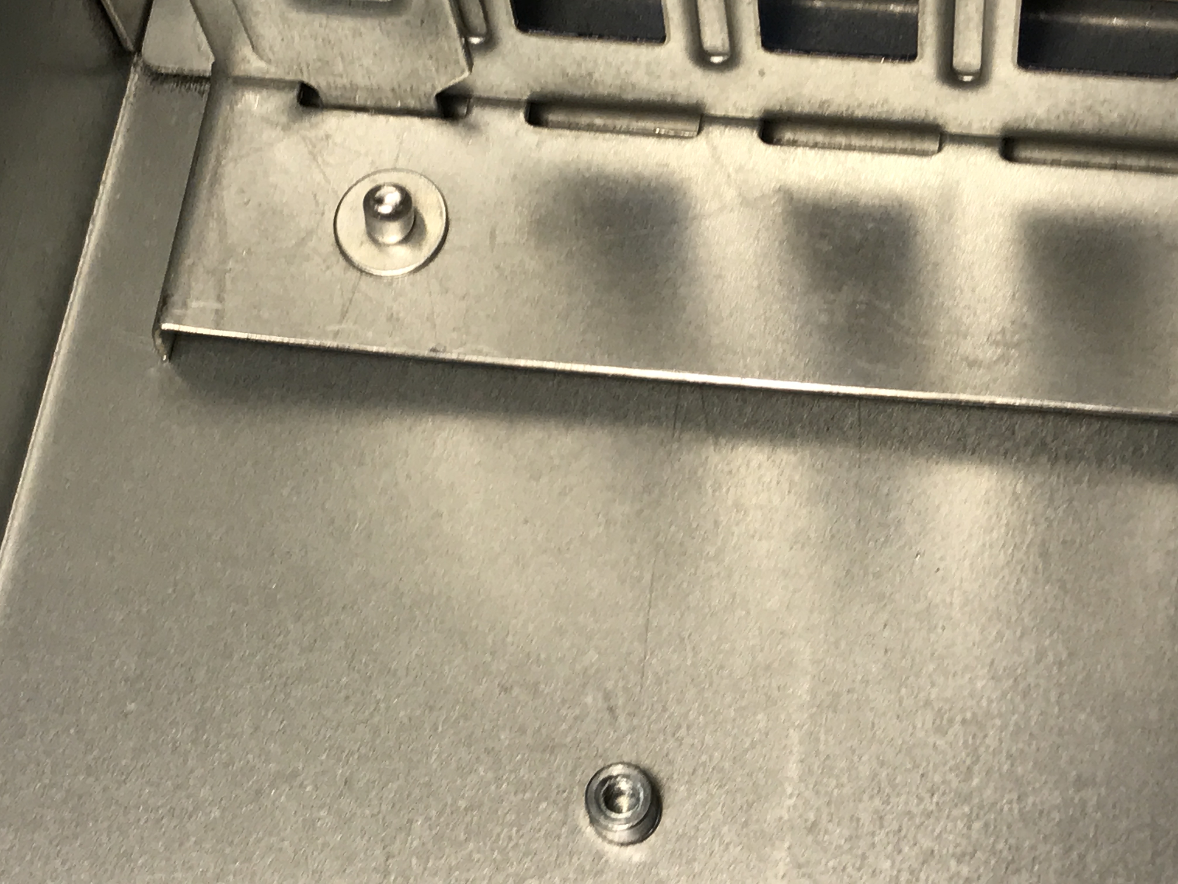
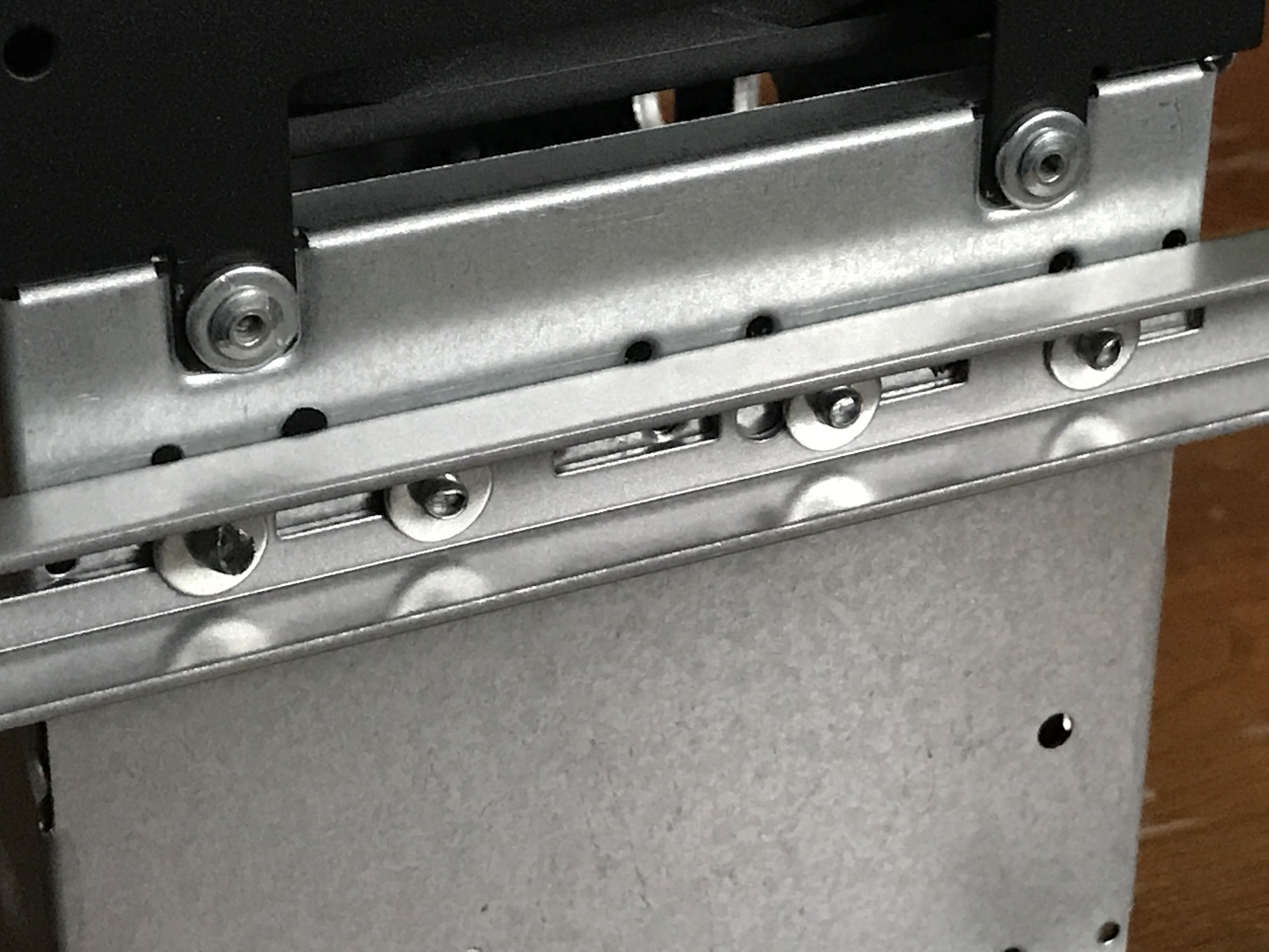
Here is a closeup. Notice the washers between this fixture and the bottom of the Rosewill.
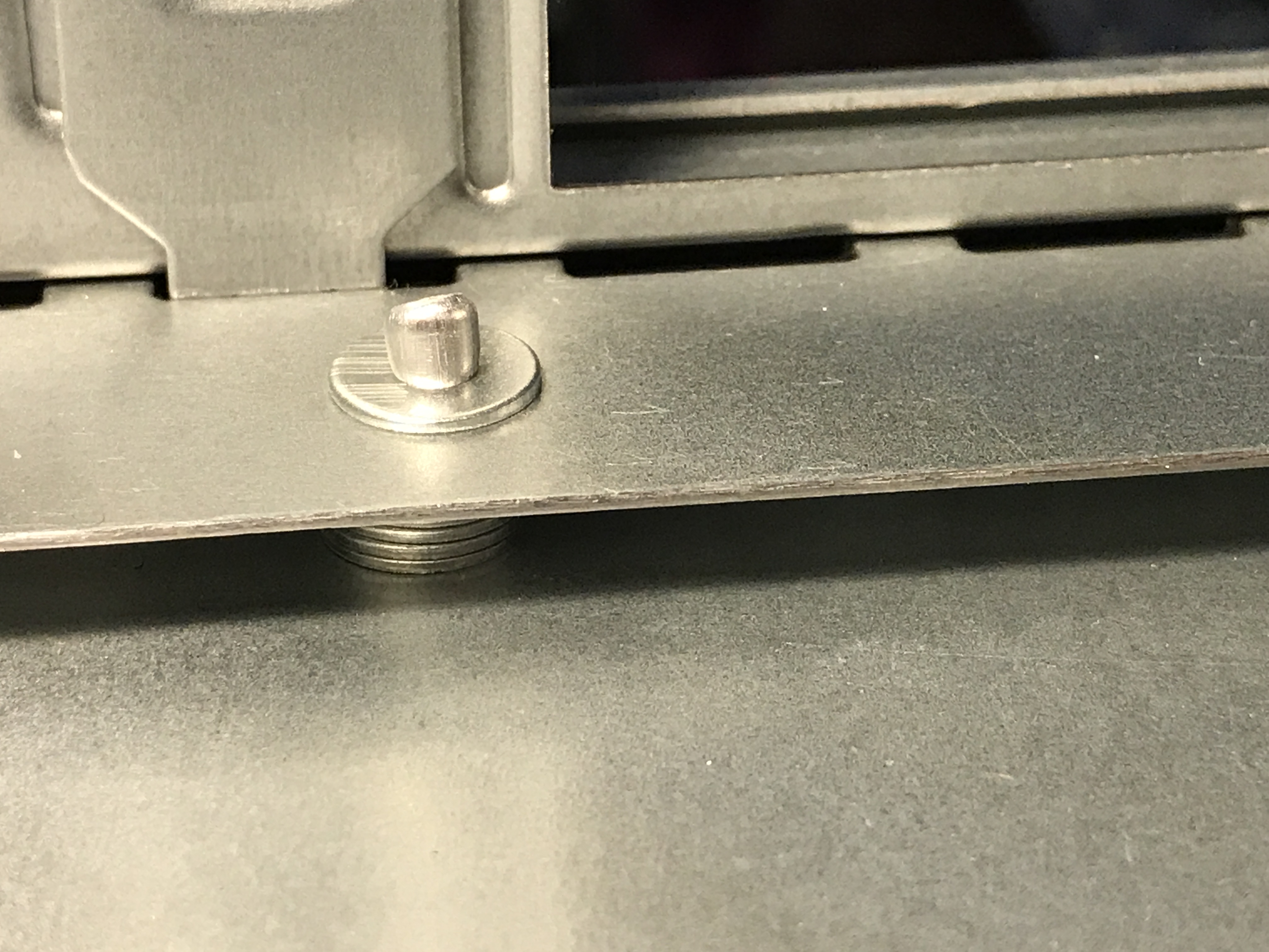
I also placed a rivet washer on the underside of the case to take up some of the length of the rivets, as they were slightly too long. In other places I also riveted from the underside of the case upward but without the bottom side washer but with just as much holding power.
I used various accessories to finish out this build. Since this DAS build is based off the original JDM ServerBuilds post on the r/Plex sub-Reddit, with many helpful posts by @manbearpig2012 the general concept is followed with some variation. You can also check out the newer ServerBuilds DAS build guide here.
Cable management mounting points were achieved with GB 1"x1" Tie-Mounting Bases from Menards. I paid about $9.50 for a pack of 100. These can be purchased on Amazon or eBay also. Initially, I thought screws or rivets would be needed to mount these securely. But the tape alone has proven to provide a very stout connection.
For a DAS PSU, I chose Seasonic FOCUS Plus 650FX 80+ Gold fully modular power supply. A cheaper PSU could have been used. But considering I purchased this for about $45, and I had great success with this exact PSU in my server, I decided to go with what works. A very attractive benefit of a fully modular PSU can be seen in the first photo of this build complete post: cable management is very clean.
As recommended in the original DAS /Plex, I use an LSI 9201-16e HBA to provide data connectivity to my server. To provide clean fit and finish connectivity on the DAS side, I use 2 port Internal SFF-8087 to External 8088 PCI mini SAS adapters, which require four External Multila Mini SAS SFF-8088 to SFF-8088 Cables.
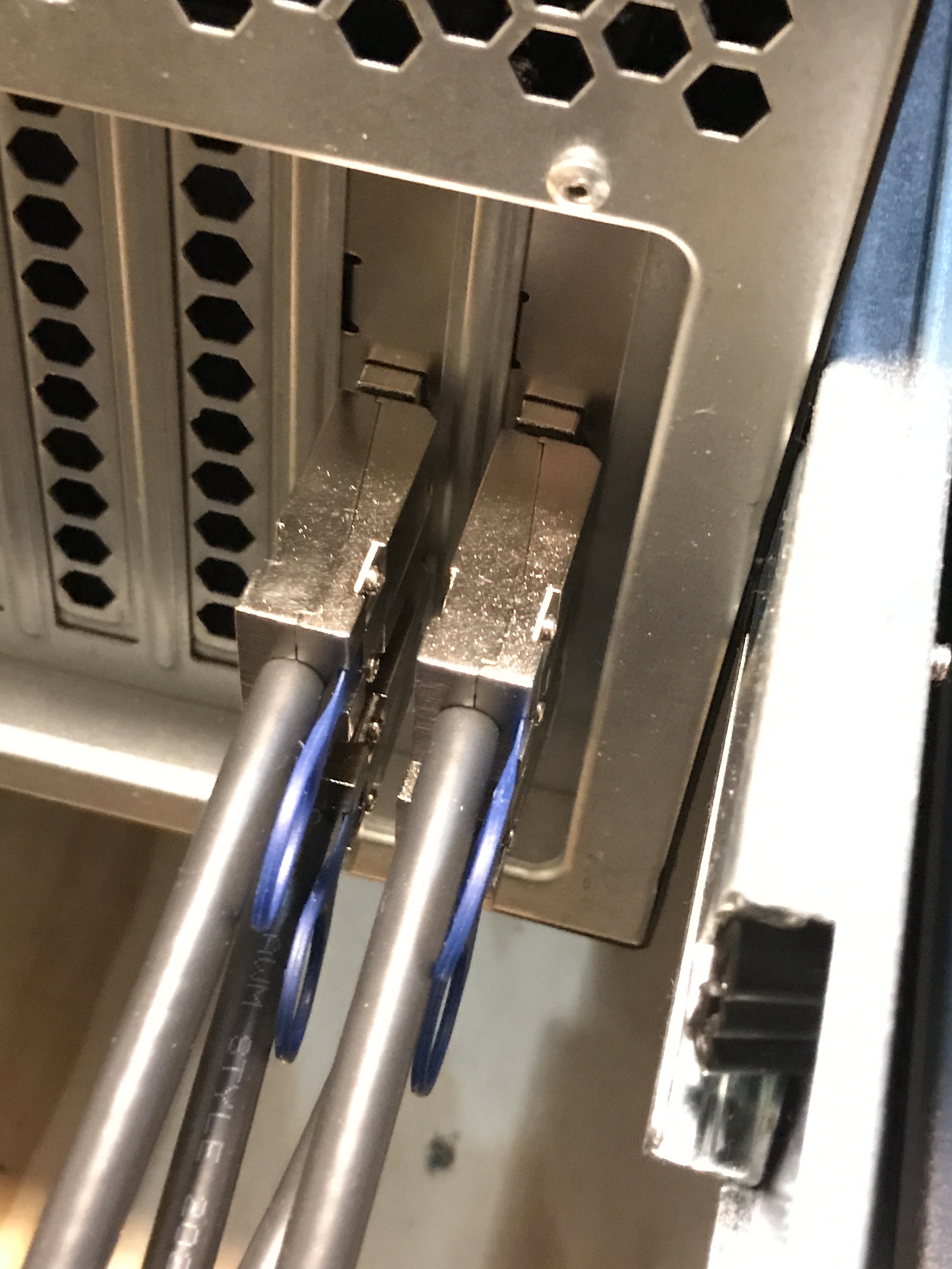
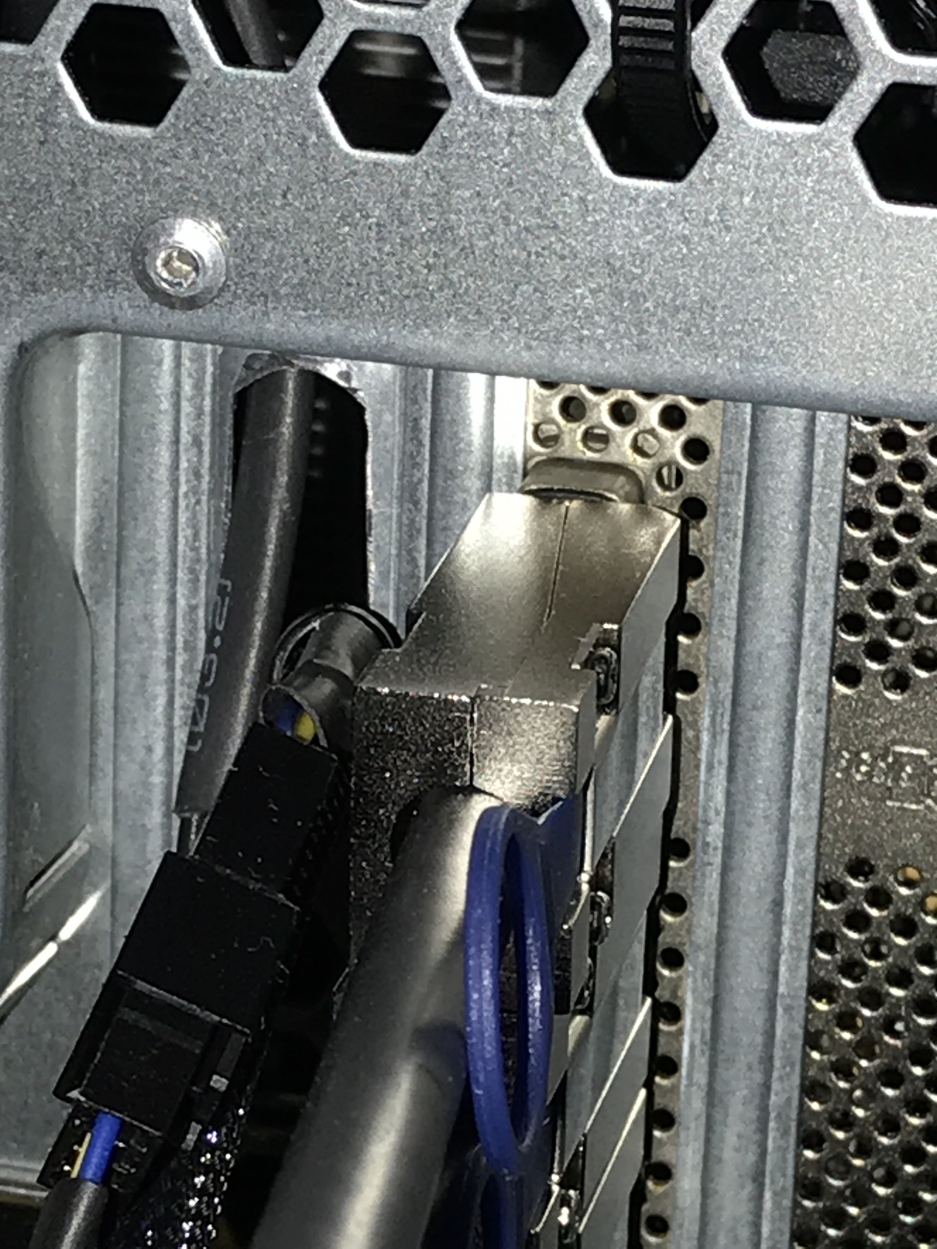
The external server side connection looks like this:
The external DAS side connection looks like this:
Flashing the LSI 9201-16e is quite easy to do. There are a number of flashing videos on Youtube, including an HBA flashing video by JDM. But if you have multiple LSI SAS HBA’s, including onboard SAS, then updating controllers individually requires the use of the -c command to choose the specific controller.
Some people advocate flashing with only one LSI SAS card connected to a motherboard and to disconnect hard drives from them. These “precautions” are not necessary. Just use the -c command. I wrote a comprehensive flashing article in the unRAID forum, aimed at beginners, detailing what to look for and how to use it.
Inside the case, I use four SFF-8087 to SATA Forward Breakout Cables. Two are 1M and two are 0.5M. Also inside the case, as with all my builds, I use Arctic F8 and F12 PWM PST fans, bought in 5-packs.
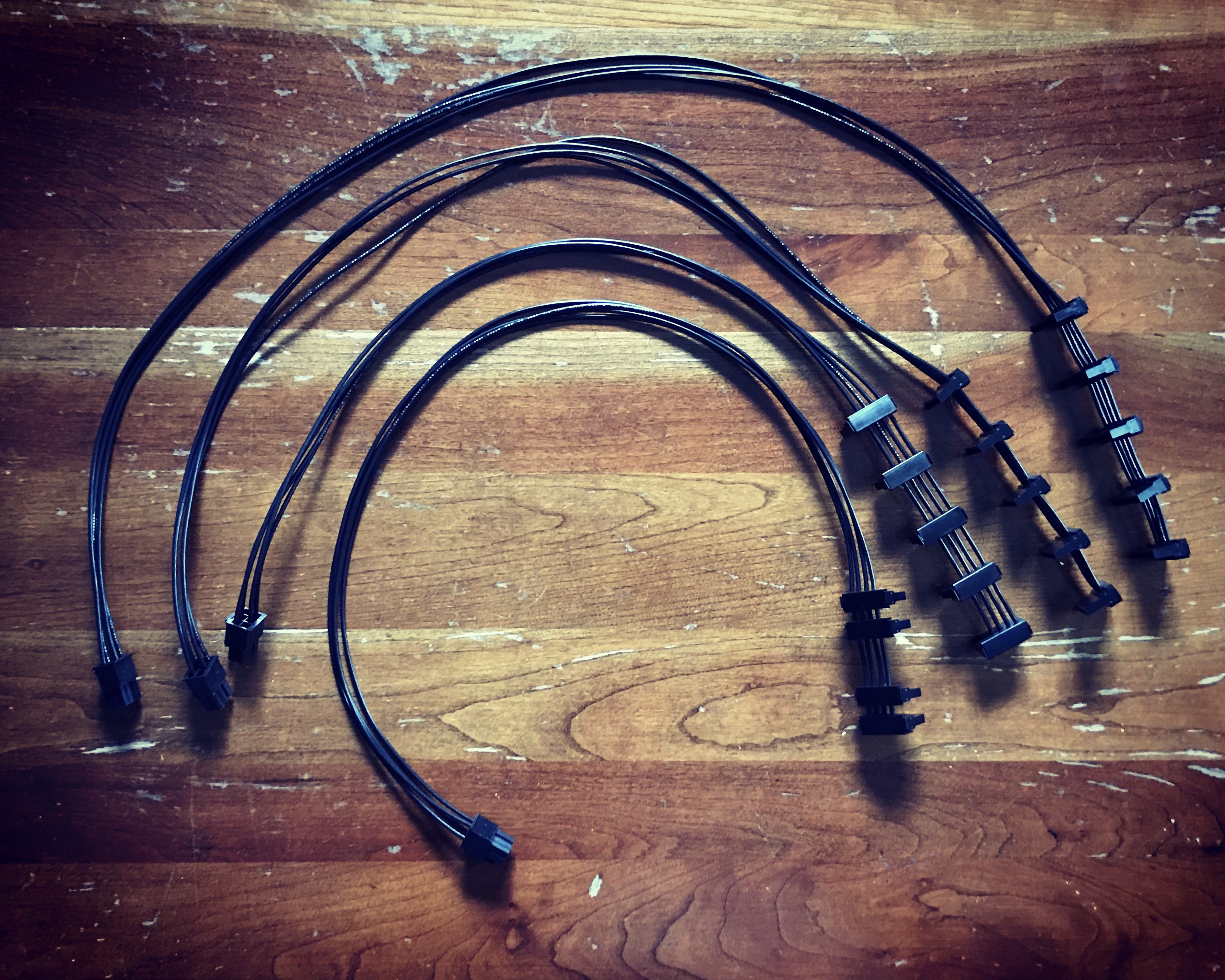
Fan connectivity between the server motherboard and the DAS case fans is achieved using fan cable extensions. I emailed Supermicro to find out the rating of the fan headers on my X8DT6-F motherboard, which turns out to be 3 watts at 12v per fan header. This means that I can easily run all my DAS fans from a single motherboard fan header. In my case, it was more convenient to use two fan headers, so that’s how I did it, using these fan extension cables from Amazon.
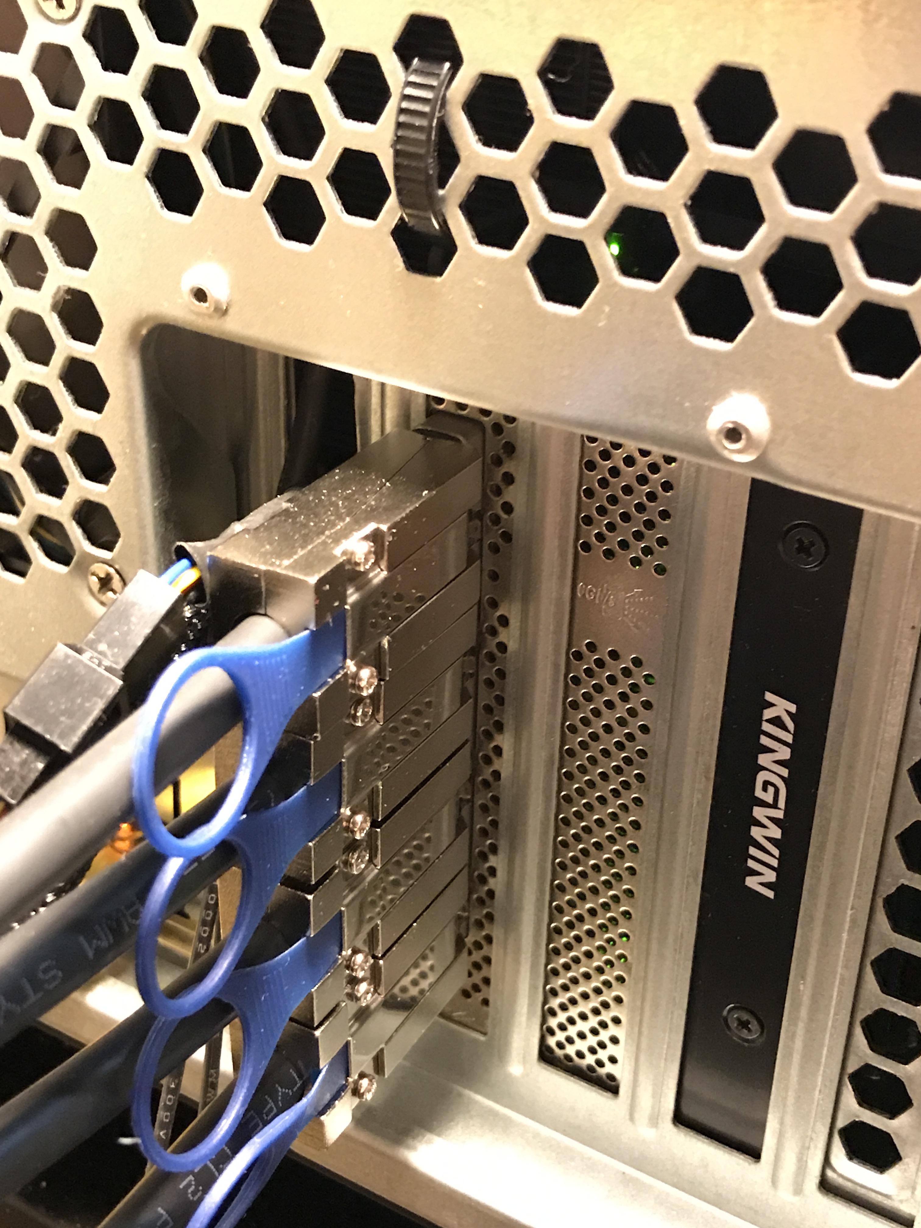
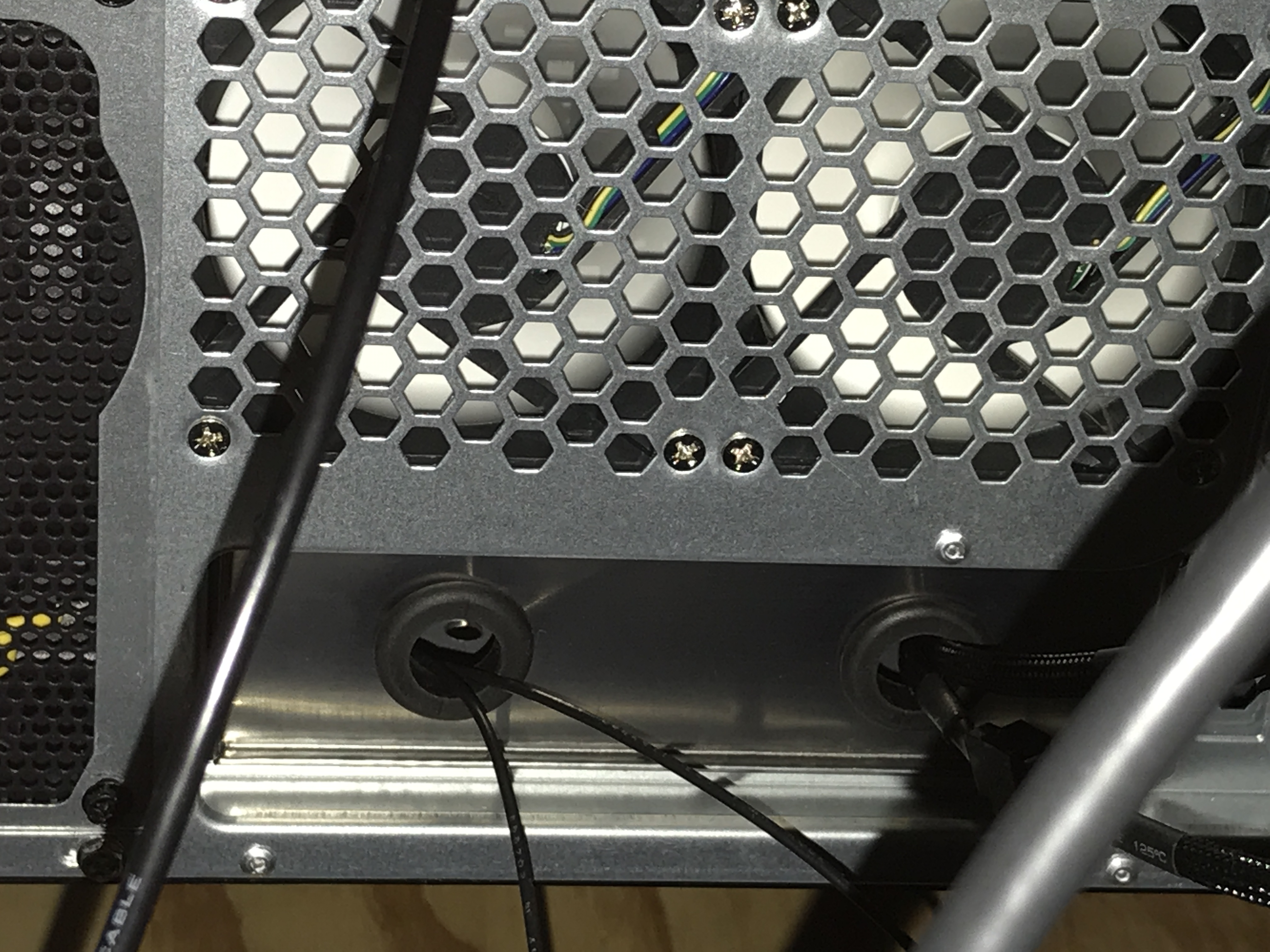
The fan extension cables were run through the back of the server by using a PCIe slot cover where I elongated existing vent holes and filed them smooth.
And on the DAS, I bought a couple of cheap IO shield, drilled two holes and installed rubber grommets to protect the wires from sharp edges. I ordered two in case I messed up one of the IO shields when drilling.
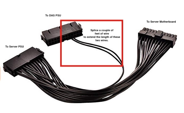
The final piece to this DAS build was getting the DAS and the server to act as one. Thanks to @Mthrboard from the JDM Discord for the suggestion, I used a Dual Power Supply 24Pin ATX Motherboard Mainboard Adapter. It works perfectly. The DAS and server truely act as one: the DAS starts and stops with the server, including being controlled by the UPS during power utility outages.
The leg that goes to the DAS PSU needs to be lengthened. I recommend these crimp connectors with built in glue lined heat shrink . And this Titan crimp tool is amazing.
A note about noise. I awoke this morning and was startled because, initially, I couldn’t hear the server and DAS running, though they’re racked in my bedroom about six feet from my bed. There are a total of 11 Arctic fans running in the server and 6 Arctic fans in the DAS, plus a total of 30 hard drives (spinners). This server/DAS combo is super silent. I understand that the Seasonic PSUs with Eco mode help reduce the noise, but they can only account for some of the noise reduction.
In short, this rack mounted DAS and server in these dual Rosewill L4500 chassis are amazing and super quiet. And with the additional cage(s) in the DAS, the full 30 bay unRAID limitation can achieved plus additional space for spinner unassigned devices for things like Time Machine backups, where array parity isn’t required. Finally, the use of a dual power supply motherboard adapter makes these two different elements act as one.