[Build Complete] NK4 to NK6 Upgrade with Dell Precision 3630 board

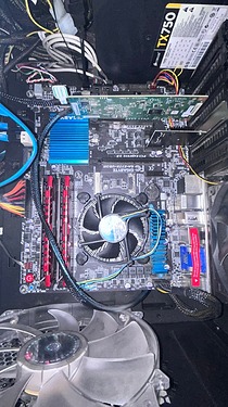
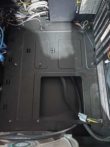
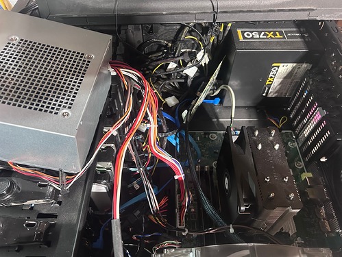
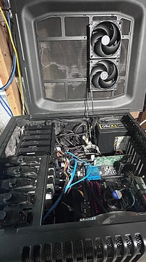
I’ve been running a NK4 adjacent build since late 2020 with an assortment of HDDs from BitDeals or others and then Rhino Drives. Here are some pics of my NK4 before I started.

I recently “upgraded” my daily driver from a Dell Optiplex 9020 Mid Tower to a Precision 3630 last winter before the NK6 Guide came out (I am a sucker for university surplus equipment.) For that build I was somewhat surprised that the newer Precision was actually LESS proprietary than the old Optiplex as it uses a 24-pin ATX power connector and appeared to have microATX hole alignments.

I hadn’t been planning an upgrade to the NK6 but then I saw a LAST ONE! eBay notification for a bare 3630 board for $35 and I foolishly had an offer accepted for $31 and then started assembling the remaining parts:

Part Model Price (each) Source
Case Cooler Master Storm Sniper (2011) $40-60? FBM (NK4 Build)
PSU Corsair TX750 V2 750w Bronze - FBM (included with CM case)
Motherboard Dell Precision 3630 Tower Motherboard IPCFL-TB P/N 0NNNCT $31 eBay
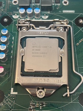
CPU Intel i5-8600 SR3X0 $50 eBay
Memory 2x 16GB UDIMM DDR4 3200MHz $25 eBay
CPU Cooler Thermalright Assassin X120 Refined SE CPU Air Cooler $19.39 Amazon (from NK6 Guide)
HBA LSI SAS 9211-8i cheap BitDeals (NK4 Build)
HDD 6x 3TB SAS/SATA $20ish? BitDeals and others (NK4 Build)
HDD 3x 8TB SAS Sun and IBM Seagate $50-55 Rhino Tech (NK4 Build)
Monitor Adapter Displayport to HDMI Adapter $5.99 Amazon
Fan Hub Cable Matters PC Case PWM Fan Hub (PC Fan Hub) 1-to-5 Way PC Fan Connector Adapter with 16-Inch Fan Cable $6.99 Amazon
Fans ARCTIC P12 PWM PST (5 Pack) $30.99 Amazon (NK4 Build)
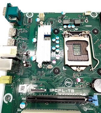
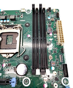
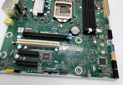
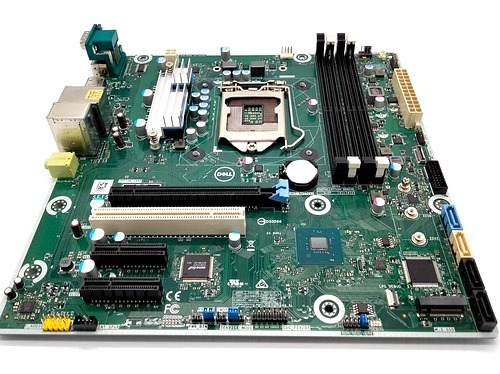
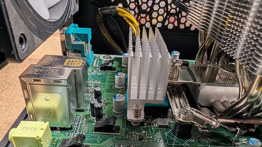
eBay 3630 board Listing Photos

Build Photos

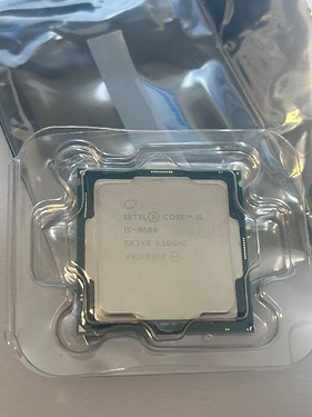
The first CPU I’ve ordered that cost enough to have a clamshell included. lol

Partial Rule #0 observance

Old motherboard out and moving standoffs

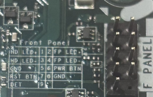
Front Panel Pinout Detail
F Panel Detail

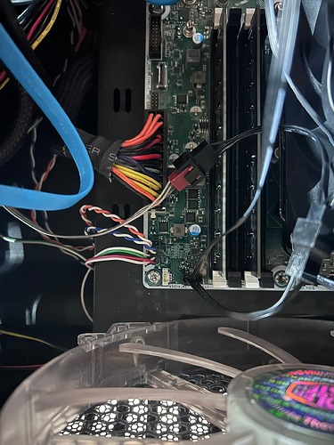
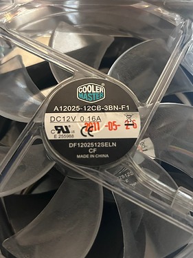
3630 Board installed connecting Front Panel power/reset button and LEDs (before I realized the 3x 5.25" to 4x 3.5" HDD cage fan failed)

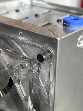
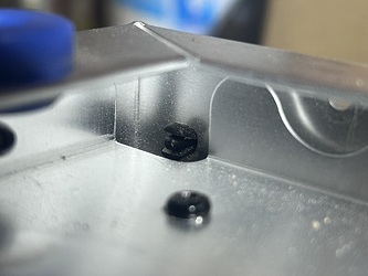
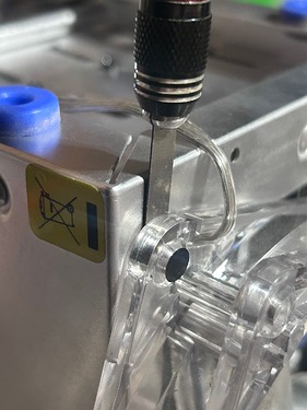
Replacing the stock CM blue LED 3-pin cage fan with Arctic P12 PWM (not pictured, zip ties replaced plastic rivets. Glad to have the rest of that 5-pack in the drawer.


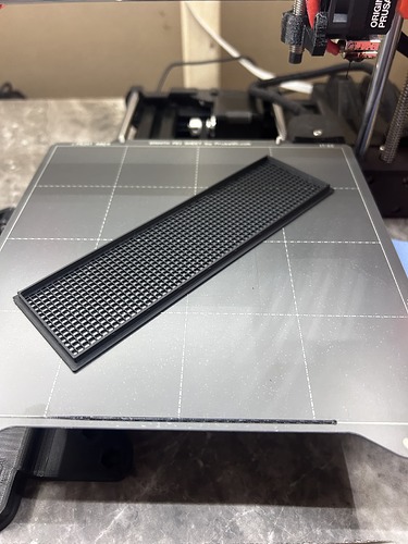
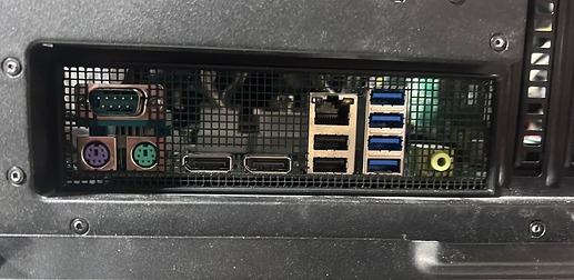
Because the IO shield is integrated with the 3630 Mid Tower case, I needed to 3D print and cut a new one (my model on Printables.)

After some trouble with maintaining the USB boot selection, I noticed the time reset back to 2019 and replaced the CMOS battery, it is much easier to do outside the case, and without the cooler installed!

Since replacing the CMOS battery and having BIOS settings last between reboots it has been running great.
image

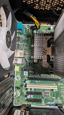
This board could be a lower cost option for the NK6 build using a microATX board with an ATX 24-pin PSU header, 1x full length PCIE 3.0 x16 slot, and 2x open ended PCI 3.0 x4 slots. There appears to be a large number of the boards available on eBay for <$50.

Two sellers with >10k feedback with p/n NNNCT @ $44.99 OBO with 103 available / 37 sold and Y2K8N @ $49.99 OBO with 72 available / 13 sold.
After I talked to @JDM_WAAAT about making this thread, he provided affiliate eBay links for those listings with the most available:

And a $99 option including the case, motherboard, and stock PSU without CPU/RAM/HDD

These stock/sold numbers and pricing appear to have been static since I bought my p/n NNNCT board from another seller on 4/4/2024.

It is worth noting there are some minor caveats and limitations for the board:

  • 4x onboard SATA ports,
  • 1x m.2 NVME slot,
  • 2x or 3x 4-pin fan headers based in at least two board revisions (before July 19 2x fan headers NNNCT, after July 2019 three 4-pin fan headers Y2K8N), and
  • rear IO shield is built into the original case so you may need to forgo an IO shield or 3D print your own.

Here are also a couple of notes on BIOS settings that I used while getting my server back up.
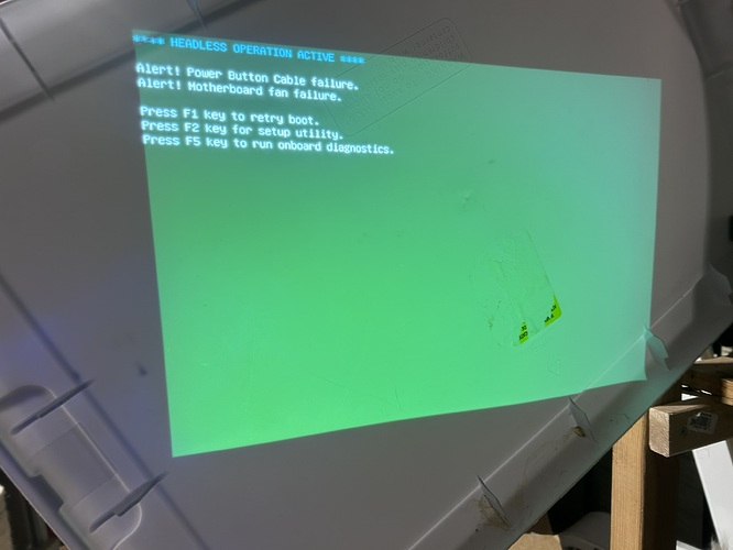
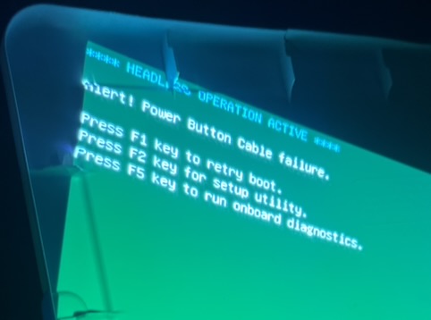
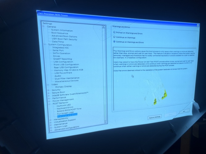
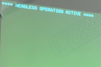
If you boot the system without a fan connected to the SYS FAN header you will get this Warning/Error on boot. The fan error requires interaction to proceed with boot. (sorry for photo quality the only thing near my server in the basement is an old projector that I use a Rubbermaid tote lid to project on :laughing:)

After plugging in the SYS FAN, I still receive this warning.
FullSizeRender

But it does not require user interaction after setting this option in the BIOS “Continue on Warnings and Errors” under POST Behavior → Warnings and Errors

This doesn’t impair any function of the power or reset buttons or status LEDs it just throws a warning at boot. I am still troubleshooting this issue and will post an update if this is resolved.

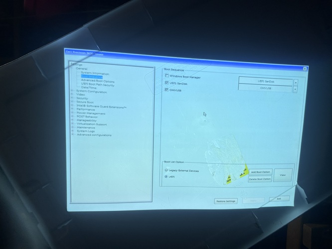
Another minor config note is that the Unraid USB EFI boot option was immediately recognized (after enabling USB boot), but my OpenMediaVault USB stick was not recognized and I had to add it as a boot option and navigate to the EFI boot file.

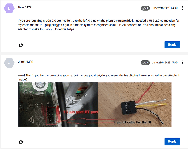
Also since my 2011 CM Storm Sniper case only has USB2 front panel ports (plus IEEE1394 and eSATA!) I can’t speak to using the USB C Type E and USB 3 headers, but I confirmed on the Discord that they appear to be standard.

Adding links to Dell support documentation.
2 Likes

The Dell setup and specifications guide also includes in-depth info about BIOS options which I didn’t cover here, but are fairly standard. Such as disabling secure boot, enabling a 5-10 second delay in POST, and disabling the full screen logo. If there is an interest and a need I could take photos of the relevant BIOS sections, but it should be somewhat self explanatory from the manual and the explanation in the BIOS sections themselves.

1 Like

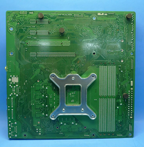
Another quick note the board has a stock backplane.

I did not remove the backplane or install the plastic backplane that is included with the Thermalright Assassin cooler. I just used the specified Intel spacers and included screws in the package.

I am fairly confident that the low profile cpu coolers with spring mounted pins won’t work with the stock backplane. As fair as I Know, generally you SHOULD NOT remove the stock backplane on a motherboard like this. So keep that in mind when looking at parts if you are using this board.

1 Like

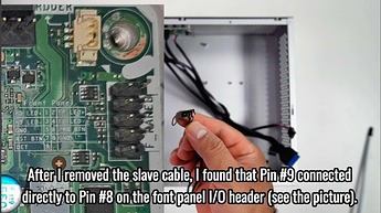
5/31/2024 update to resolve “Power Button Cable failure” warning during boot.

After watching this 3630 Case Swap YouTube video @stuffwhy found about a month ago, this was shown at approximately 8:13 in the video (Dell Precision T3630 to 7.3 Liters HTPC Case swap)

In the video he removes the power button from the front panel and solders the lead directly to the PCB contact, which would probably work significantly better in the small HTPC case used in the video, but wasn’t workable for my case.

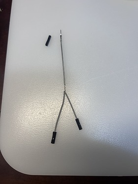
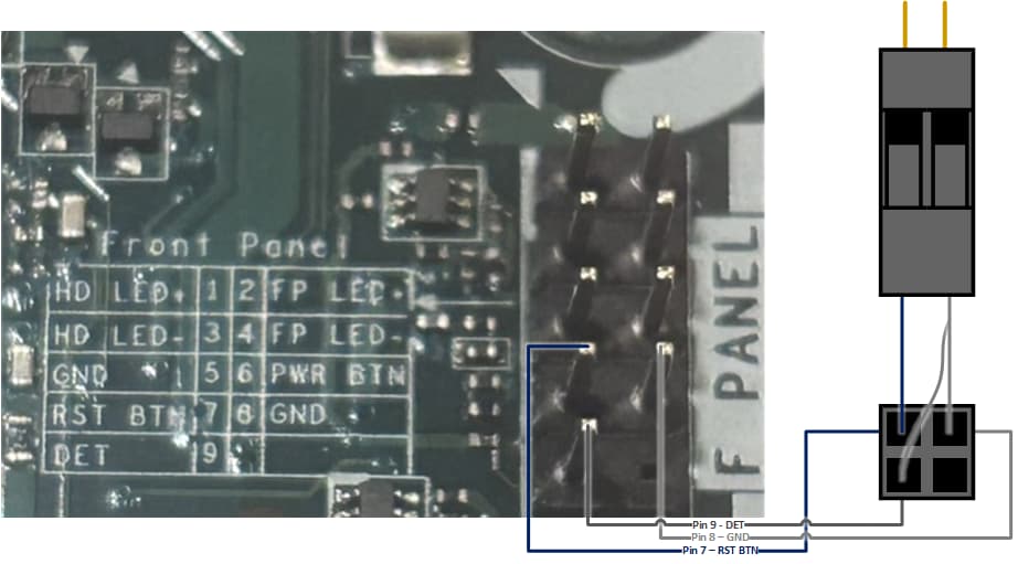
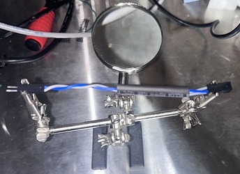
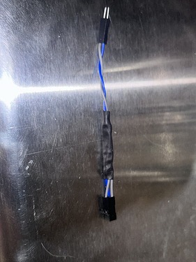
Instead I spliced two dupont cables together with 2x female ends to plug into the board header on pins #8 GND and #9 DET as labeled on the 3630 mobo silkscreen.

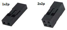
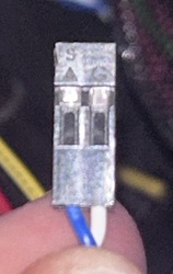
For ease of plugging in my front panel cables I placed the female ends into a 2x2p Dupont connector housing and the male end into a 1x2p connector.
Dupont_connectors

I also populated a third position in the 2x2p connector with a Dupont cable from pin #7 RST BTN and left the the fourth position open as the 3630 board header has no pin #10.

Here is a very poor diagram attempting to show how I wired things.

The 1x2p male ends will then plug into my case front panel reset button cable that would normally plug directly into the motherboard header (since pin #8 is GND it doesn’t seem to matter at all if it connected to the GND wire that is paired with the PWR BTN or RST BTN cable, at least for me.)

I then soldered the splice together and added shrink tubing to the wire assembly.

After testing continuity with my multimeter I installed the cable and powered up my NK6. I was greeted with no warnings or errors during the boot process!

Of course this isn’t strictly necessary to boot successfully since the BIOS can be set to not hang on the power button cable warning, as I covered in the original post, but I wanted to solder some stuff and already had way to many dupont cables and connectors laying around from past raspberry pi and other sbc projects.

If there are any questions or corrections please hit me up on discord or reply here!

1 Like

This is awesome, thanks so much for such an awesome guide and cool build!

Been chatting on the discord but I picked up 2 of these boards and will be getting a 3rd for a proxmox cluster :slight_smile:

1 Like

Thanks! It was fun to document and make the thread and I’m glad it’s working for you. Honestly I wasn’t planning on building an NK6 but the $31 offer for the board was just too cheap to pass up and mess around with lol

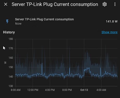
Here is a comparison between power consumption from the NK4 LGA1155 i5-2500/24GB DDR3 ram/Gigabyte GA-Z77X-UD3H mobo to the current 3630 NK6 i5-8600/32GB DDR4 ram/3630 0NNNCT mobo configuration. All measurements are shown in my HomeAssistant dashboard using a TP-Link Kasa Smart Plug Mini 15A EP25P4.
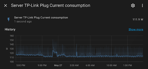
Unless noted for the bare board the before and after comparison has 11 spinners (seven 3TB SATA/SAS HDDs and four 8TB SATA/SAS, one each of the 3TB and 8TB not mentioned above because they aren’t part of my existing snapraid array and are showing signs of failure), the LSI 9211-8i HBA, and two SATA 2.5" SSDs.

Here is the NK4 consumption with an idle consumption of 141.8w with peaks under load reaching nearly 175w.

After installing the NK6 3630 board idle consumption was 111.9w with peaks under load rarely exceeding 145w.

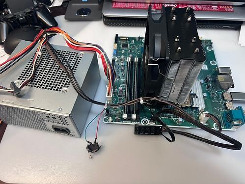
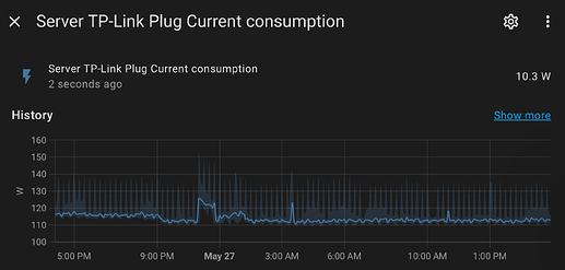
I was also asked by fence on the discord what the bare board consumption was without any drives or PCIe cards. In the interest of science I connected the stock PSU I had pulled from my 3630 desktop and connected it just to the board and CPU with only an unconfigured Unraid USB stick connected, while I took the system down to install the power cable assembly mod.

After booting and giving things a moment to settle, idle consumption appeared to be just 10.3w!


Ignore the history part of the chart as it is essentially identical to the previous chart since they were minutes apart.

This was all posted on discord at different times as well, but I wanted to put it in one place because I got sick of looking for it whenever I thought about it. lol

2 Likes

Pretty handy. Thanks.

1 Like

Thank you for this post, I’m in the process putting my 3630 in a bigger case to add more HDD’s to it. Modified my cast and remove the USB and Audio ports that it came with and got the Dell Audio, SD Card, USB C, 3.0 and the other one’s from the front panel, the power switch is all I have left to connect.

Thanks again,

MustangMan

1 Like

If you are soldering adverse, here are a couple of options for a Dupont jumper cable 2x female header to 1x male header Y cable assembly. This could be placed on pin 8 GND and pin 9 DET and then plugged into the negative lead on your case power button wiring.

Here are two listings for a 2-pack made by the same vendor, with one on etsy and one on MakerProducts. Makerproducts has $2 flat rate shipping in the US.
https://www.etsy.com/listing/1333156495/dupont-y-cable-splitter-jumper-wire-male

Here is another listing on Moddiy:

NOTE: I haven’t ordered any of these and have no experience with MakerProducts or Moddiy. But it looks like it should work as well as most other dupont cables.

1 Like

Thanks! Sorry didn’t see this before I posted the update but there are a couple of off the shelf options for the power cable fix as well. Good luck!

Hi,

This is really Good, I really appreciate this awesome guide and cool build.

Thanks

1 Like